There are several ways to measure level amongst which are Guided Wave Rader Level measurement, Radar Level Measurement, Ultrasonic Level Measurement, Servo level measurement and many more. But still, one of the most common and robust ways to measure level is by means of hydrostatic level measurement making use of differential pressure.
With hydrostatic pressure measurement it is possible to measure level in vessels, tanks, reactors etc. This is one of the most common applications for Diaphragm Seals. Also the hydrostatic pressure can be used to measure changes in density. Next to level, it can also be used for interface measurement, or to measure mass of a process media inside a tank.
The diaphragm seal system measurement is unaffected by agitation, foaming, or internal obstacles. The diaphragm seals system extend limitations of the pressure instrument due to process conditions such as high and low temperatures, corrosive processes, viscous mediums, and hygienic applications.

With this mounting style the differential pressure transmitter is placed in between of the two no...
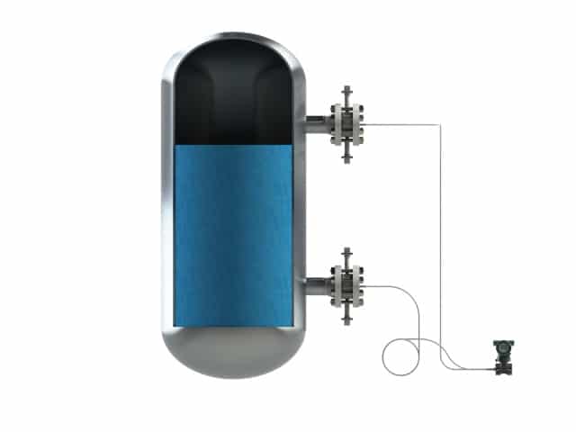
With this mounting style the differential pressure transmitter is placed in between of the two nozzles.
This mounting style has the advantage that is can keep the capillaries as short as possible, thus reducing the ambient temperature exposed to the capillaries. The downside may be that in this configuration the instrument is not protected against vacuum situations and can only withstand a limited vacuum.
With this mounting style the differential pressure transmitter is placed ...
With this mounting style the differential pressure transmitter is placed in between of the two nozzles.
This mounting style has the advantage that is can keep the capillaries as short as possible, thus reducing the ambient temperature exposed to the capillaries. The downside may be that in this configuration the instrument is not protected against vacuum situations and can only withstand a limited vacuum.
WIth this measurement style the differential pressure transmitter is placed below the lowest nozz...
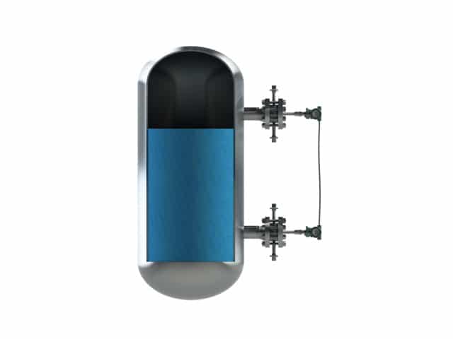
WIth this measurement style the differential pressure transmitter is placed below the lowest nozzle.
This mounting style allows a full vacuum process pressure without the risk of damaging the pressure transmitter. This configuration means that capillaries need to be longer. This measurement style is often recommended in combination with a full welded construction.
WIth this measurement style the differential pressure transmitter is plac...
WIth this measurement style the differential pressure transmitter is placed below the lowest nozzle.
This mounting style allows a full vacuum process pressure without the risk of damaging the pressure transmitter. This configuration means that capillaries need to be longer. This measurement style is often recommended in combination with a full welded construction.

With DP level style 3 the transmitter is placed above the upper nozzle.
This is situation...
With DP level style 3 the transmitter is placed above the upper nozzle.
This is situation is a specific one and quite uncommon. This due to the fact that this set-up can lead to damage to the pressure instrument due to the negative pressure it generated due to the liquid column created by the (long) capillaries on both sides.
With DP level style 3 the transmitter is placed above the upper nozzle. <...
With DP level style 3 the transmitter is placed above the upper nozzle.
This is situation is a specific one and quite uncommon. This due to the fact that this set-up can lead to damage to the pressure instrument due to the negative pressure it generated due to the liquid column created by the (long) capillaries on both sides.
Compensated systems are build to reduce the mounting effect in an unbalanced system.
With ...
Compensated systems are build to reduce the mounting effect in an unbalanced system.
With the compensation system the temperature effect on the remote mounted side can be compensated on the direct mounted side.
Compensated systems are build to reduce the mounting effect in an unbalan...
Compensated systems are build to reduce the mounting effect in an unbalanced system.
With the compensation system the temperature effect on the remote mounted side can be compensated on the direct mounted side.
Unbalanced systems are unwanted due to the extra inaccuracies that can occur due to the different...
Unbalanced systems are unwanted due to the extra inaccuracies that can occur due to the different capillary lengths.
In changing process conditions, the different seal sides are exposed to different conditions, increasing the TPE and the uncertainty. However in some (stable) situations and under certain conditions it could be a acceptable solution.
A direct mount is of course more easy to mount, and possibly slightly more economical. However a durable and reliable pressure measurement should be more important.
Unbalanced systems are unwanted due to the extra inaccuracies that can oc...
Unbalanced systems are unwanted due to the extra inaccuracies that can occur due to the different capillary lengths.
In changing process conditions, the different seal sides are exposed to different conditions, increasing the TPE and the uncertainty. However in some (stable) situations and under certain conditions it could be a acceptable solution.
A direct mount is of course more easy to mount, and possibly slightly more economical. However a durable and reliable pressure measurement should be more important.
Style 6 is a gauge pressure direct mount situation. The diaphragm seal and the pressure transmitt...
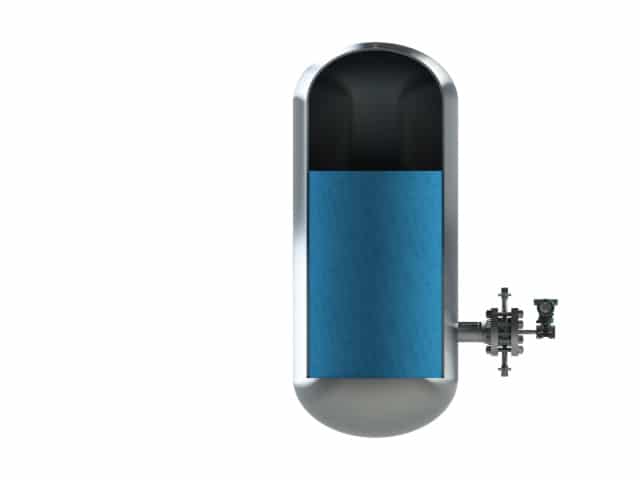
Style 6 is a gauge pressure direct mount situation. The diaphragm seal and the pressure transmitter are mounted on the same level. This setup is used in level measurement in open tank situation.
Style 6 is a gauge pressure direct mount situation. The diaphragm seal an...
Style 6 is a gauge pressure direct mount situation. The diaphragm seal and the pressure transmitter are mounted on the same level. This setup is used in level measurement in open tank situation.
This style uses two GP pressure transmitters where the two transmitters are connected via a elect...
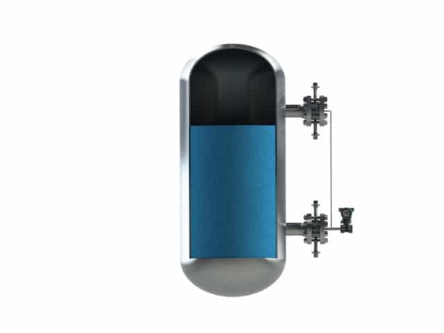
This style uses two GP pressure transmitters where the two transmitters are connected via a electrical cable. The setup is an Master – Slave situation where the differential pressure is calculated by the system and gives this as an output signal. This system is specially suited for large height differences where capillary systems such as tall tanks with nozzles are mounted more then 15 meters apart.
This style uses two GP pressure transmitters where the two transmitters a...
This style uses two GP pressure transmitters where the two transmitters are connected via a electrical cable. The setup is an Master – Slave situation where the differential pressure is calculated by the system and gives this as an output signal. This system is specially suited for large height differences where capillary systems such as tall tanks with nozzles are mounted more then 15 meters apart.
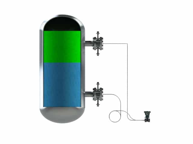
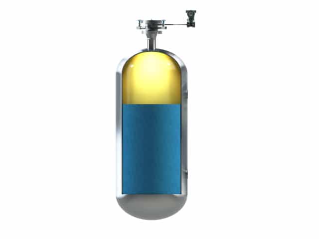
In a vessel containing two fluids with different densities, it is important to determine where th...
In a vessel containing two fluids with different densities, it is important to determine where the interface of these two fluids is situated. The latter can be done with a dP transmitter equipped with two diaphragm seals (a dP transmitter with impulse lines will give more erroneous measurement). The interface dP span is defined as the hydrostatic column in the vessel assumed being full with the heaviest fluid (at the bottom) minus the hydrostatic column in the vessel assumed being full with the lightest fluid (at the top). Care should be taken for those applications where the difference in density between the two fluids is very small, resulting in a very low dP span, in that case the mounting effect could become very high, this can be overcome by applying tracing to the capillaries. The correct answers, results can be found in BaseCal.”
In a vessel containing two fluids with different densities, it is importa...
In a vessel containing two fluids with different densities, it is important to determine where the interface of these two fluids is situated. The latter can be done with a dP transmitter equipped with two diaphragm seals (a dP transmitter with impulse lines will give more erroneous measurement). The interface dP span is defined as the hydrostatic column in the vessel assumed being full with the heaviest fluid (at the bottom) minus the hydrostatic column in the vessel assumed being full with the lightest fluid (at the top). Care should be taken for those applications where the difference in density between the two fluids is very small, resulting in a very low dP span, in that case the mounting effect could become very high, this can be overcome by applying tracing to the capillaries. The correct answers, results can be found in BaseCal.”
Measuring pressure is very common throughout industrial processes and it must be understood what reference any particular reading is made from as this can drastically affect the accuracy of the measurement.
Gauge Pressure means that the pressure measured is relative to the atmospheric pressure at the location of the measurement. It is zero referenced against atmospheric pressure, so it is equal to absolute pressure plus atmospheric pressure. Since gauge pressure is zero-referenced against ambient air (or atmospheric) pressure, so gauge pressure readings include the pressure from the weight of the atmosphere. That means that the gauge pressure varies according to height above sea level as well as to weather conditions. In order to make clear that it concerns gauge pressure ‘g’ is added to the unit of pressure, e.g.: mbarg; PSIg
Absolute Pressure is zero referenced against an absolute of full vacuum, with no atmospheric pressure. So it is equal to gauge pressure minus atmospheric pressure. In order to make clear that it concerns absolute pressure an ‘a’ is added to the unit of measure, e.g.: mbara; PSIa
Style 6 is a gauge pressure direct mount situation. The diaphragm seal and the pressure transmitt...
Style 6 is a gauge pressure direct mount situation. The diaphragm seal and the pressure transmitter are mounted on the same level. This setup is used in level measurement in open tank situation.
Style 6 is a gauge pressure direct mount situation. The diaphragm seal an...
Style 6 is a gauge pressure direct mount situation. The diaphragm seal and the pressure transmitter are mounted on the same level. This setup is used in level measurement in open tank situation.
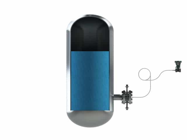
Style 7 is a gauge pressure remote mount situation. The pressure transmitter is mounted above t...
Style 7 is a gauge pressure remote mount situation. The pressure transmitter is mounted above the diaphragm seal level. This setup is used in level measurement in open tank situation.
Style 7 is a gauge pressure remote mount situation. The pressure transm...
Style 7 is a gauge pressure remote mount situation. The pressure transmitter is mounted above the diaphragm seal level. This setup is used in level measurement in open tank situation.
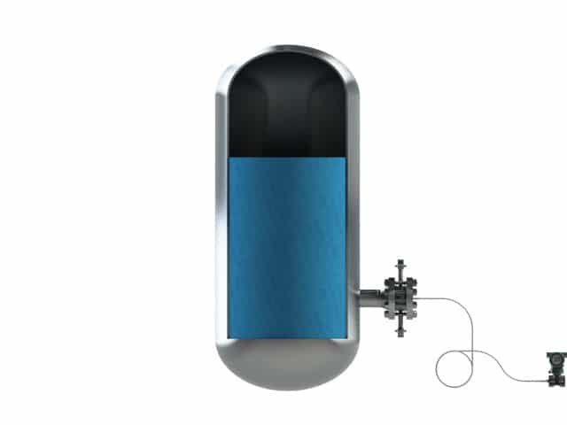
Style 8 is a gauge pressure remote mount situation. The pressure transmitter is mounted below t...
Style 8 is a gauge pressure remote mount situation. The pressure transmitter is mounted below the diaphragm seal level. This setup is used in level measurement in open tank situation.
Style 8 is a gauge pressure remote mount situation. The pressure transm...
Style 8 is a gauge pressure remote mount situation. The pressure transmitter is mounted below the diaphragm seal level. This setup is used in level measurement in open tank situation.
Style 8 LGP is a gauge pressure remote mount situation. The LGP solution helps in measuring a ver...
Style 8 LGP is a gauge pressure remote mount situation. The LGP solution helps in measuring a very low span with reducing the ambient temperature and ambient pressure effect by compensating those. This situation is commonly used to measure the nitrogen blanketing in tanks.
Style 8 LGP is a gauge pressure remote mount situation. The LGP solution ...
Style 8 LGP is a gauge pressure remote mount situation. The LGP solution helps in measuring a very low span with reducing the ambient temperature and ambient pressure effect by compensating those. This situation is commonly used to measure the nitrogen blanketing in tanks.
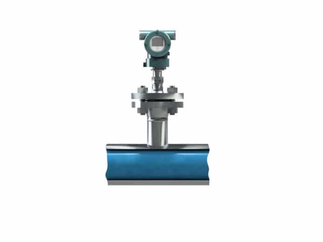
There are several ways to measure flow amongst which are Coriolis measurement, Vortex measurement, Ultrasonic Level Measurement, and many more. Also differential pressure can be used to measure the flow of a system.
With differential pressure measurement it is possible to measure the flow in a system. Although flow measurement with differential pressure and diaphragm seals might not be the most ideal solution to measure flow, in some situations, it can can be very useful. especially in case of very elevated process temperatures or in case of very corrosive applications, make flow measurement with DP and diaphragm seals recommended.
The challenge is that with DP flow, the square root of the dP is taken, which takes roughly 25% of the dP span and thus 50% of the flow.
But we can help you how you can make these applications work.
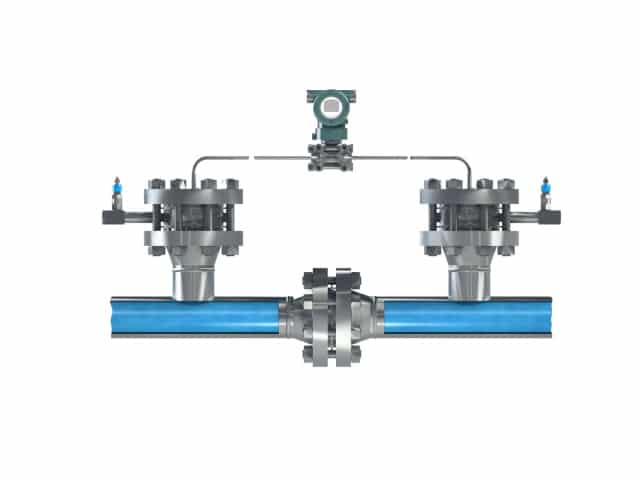
With this style the differential pressure transmitter is placed in between of the two nozzles.
With this style the differential pressure transmitter is placed in between of the two nozzles.
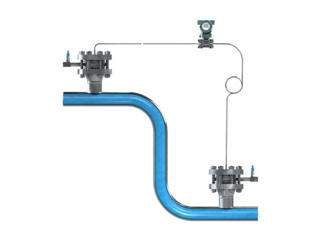
With this style the differential pressure transmitter is placed in betwee...
With this style the differential pressure transmitter is placed in between of the two nozzles.
With this style the differential pressure transmitter is placed in between of the two nozzles.
With this style the differential pressure transmitter is placed in between of the two nozzles.
With this style the differential pressure transmitter is placed in betwee...
With this style the differential pressure transmitter is placed in between of the two nozzles.